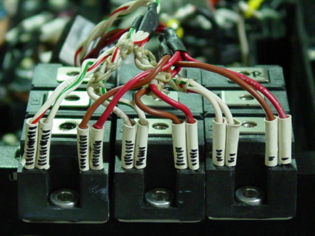
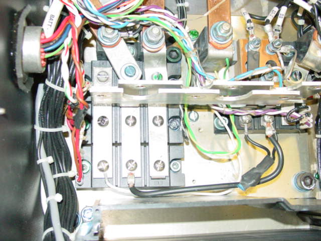
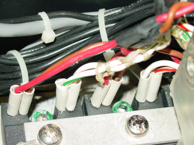
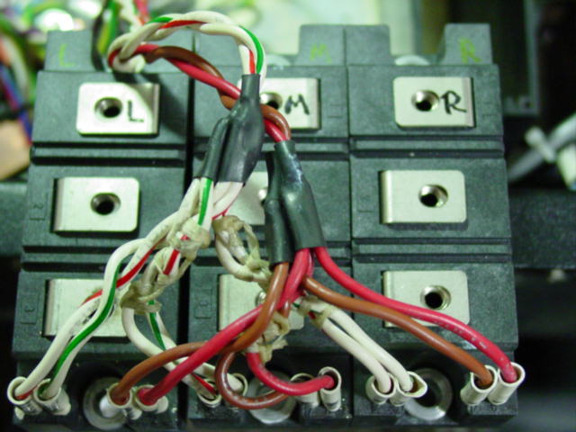
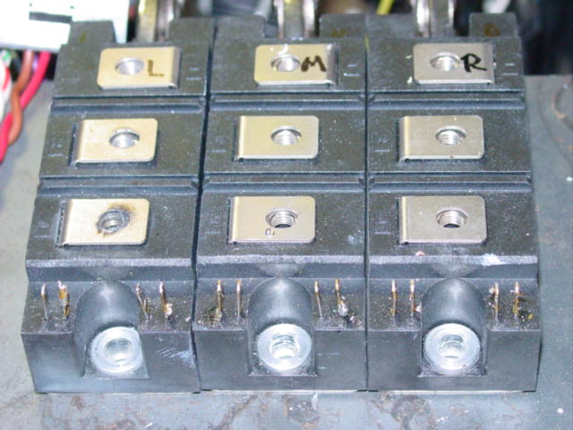
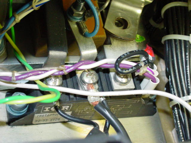
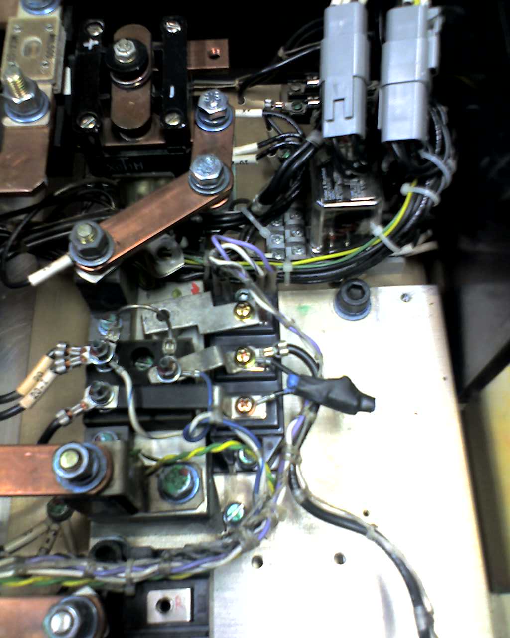
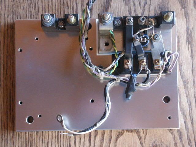
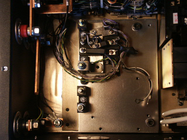
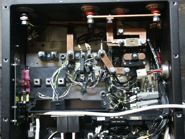
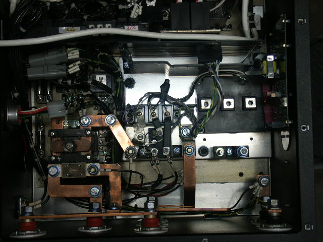
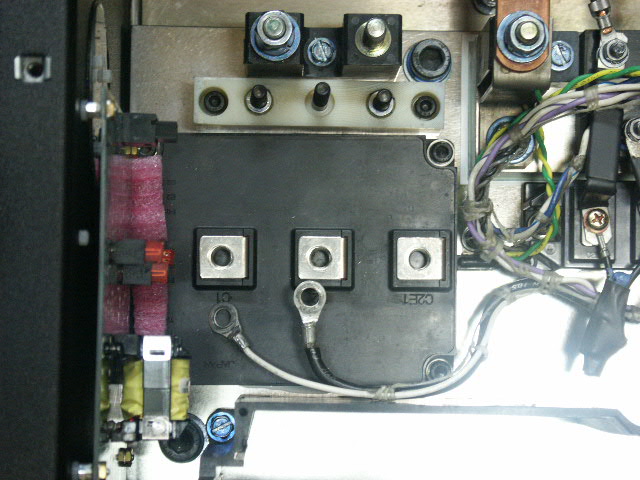
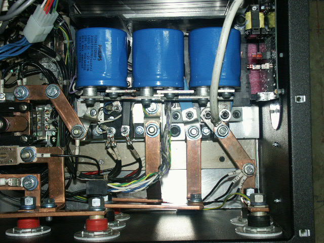
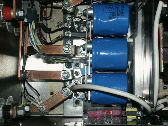
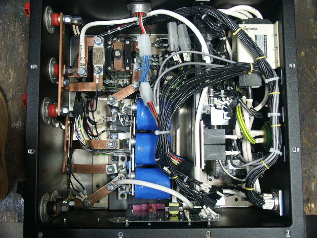
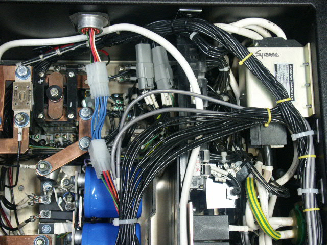
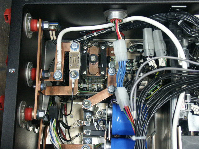
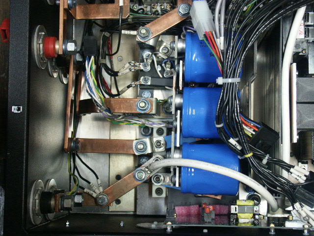
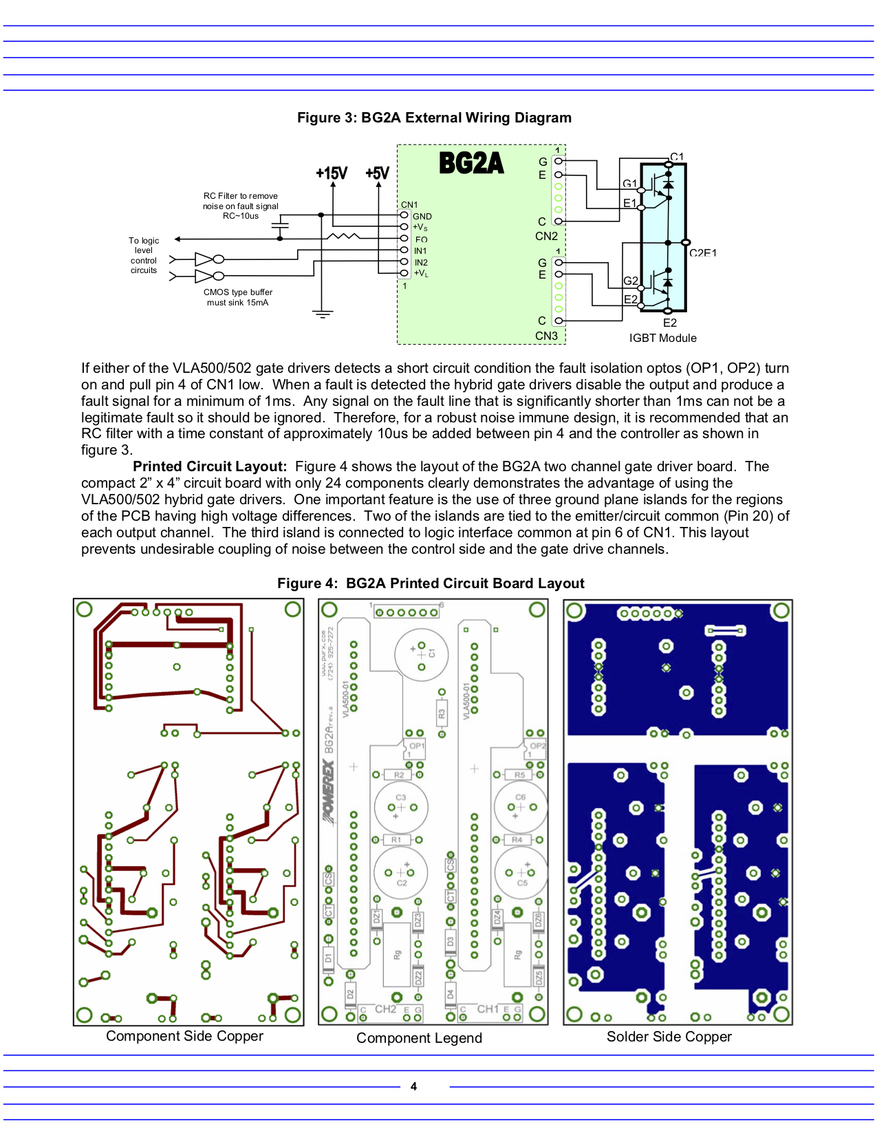
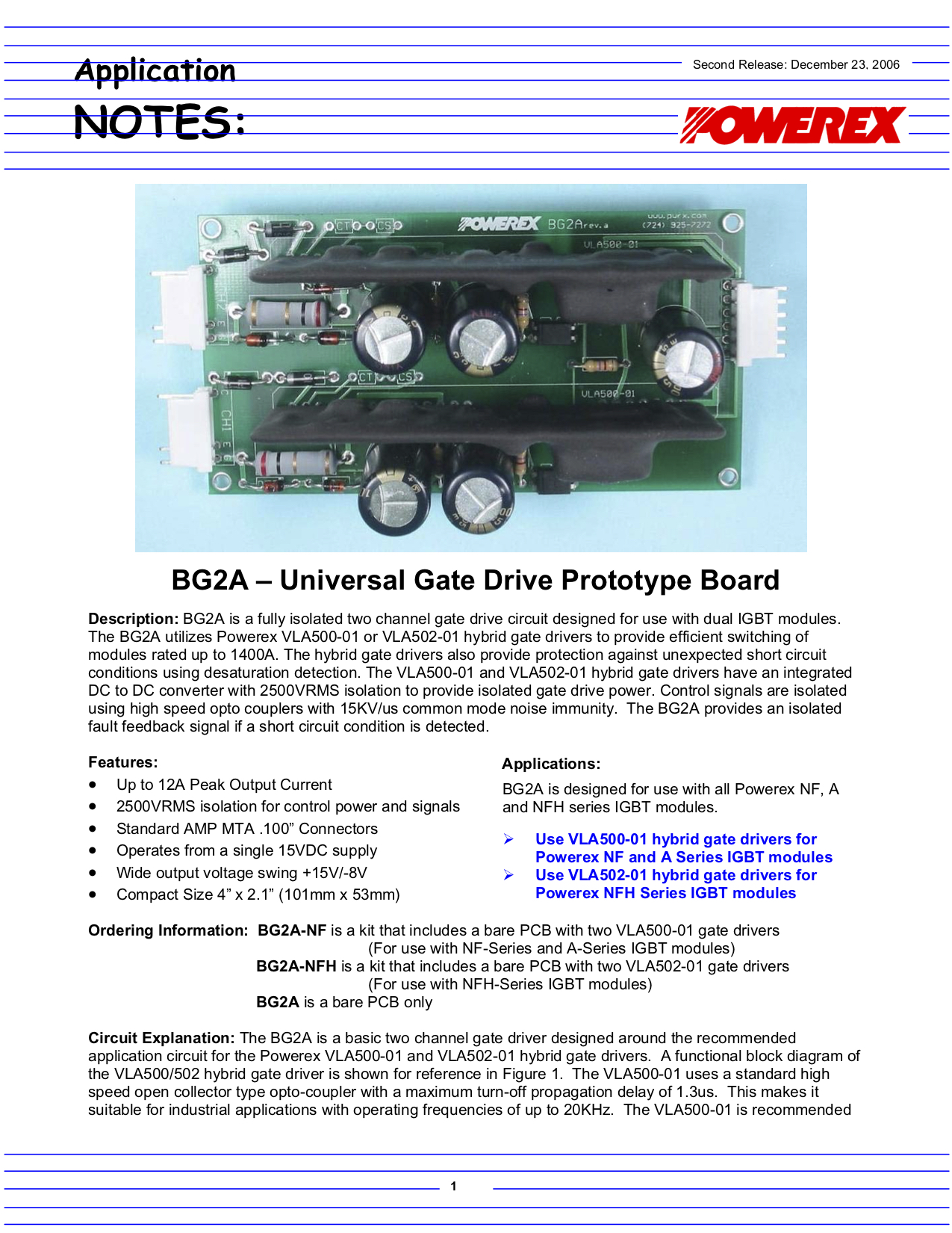
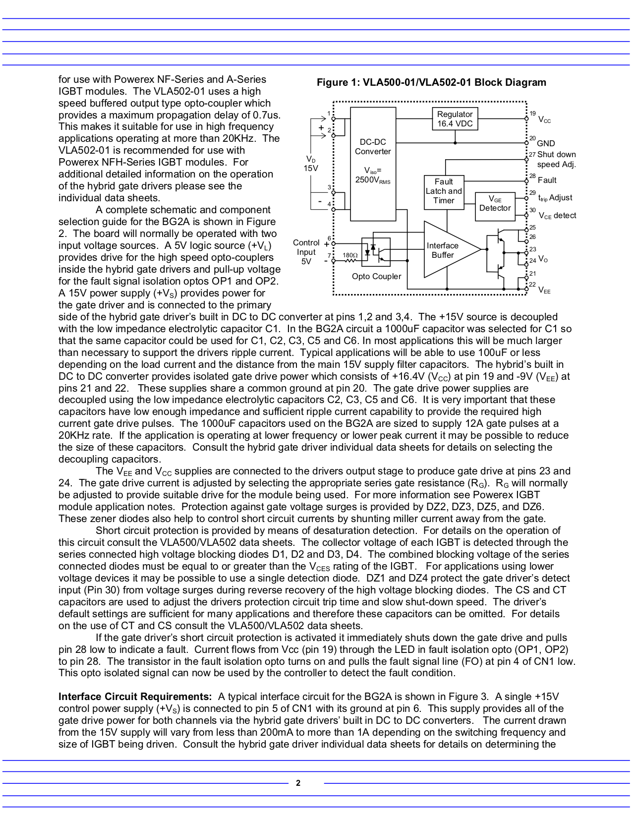
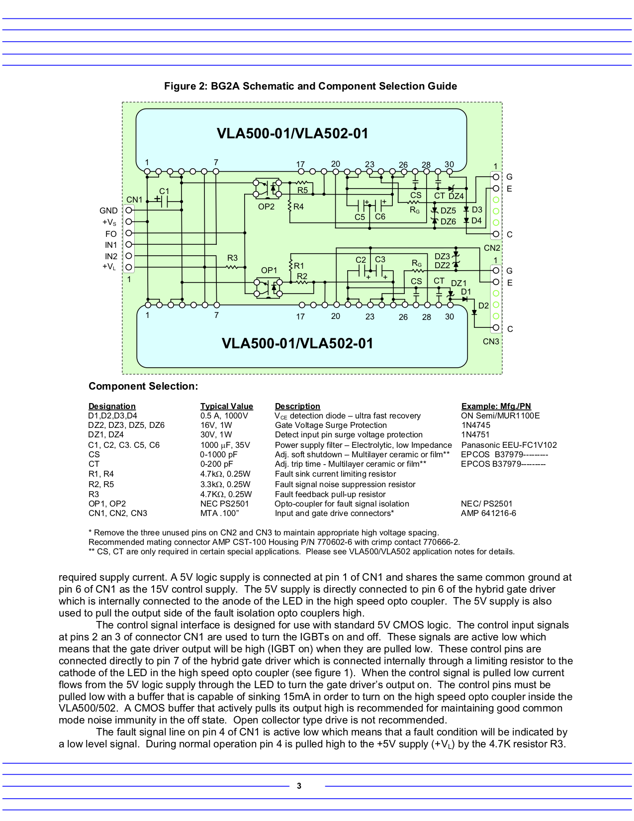
The TEVans original IGBT triple IN-A-PAK configuration shown here to the left side of the picture.
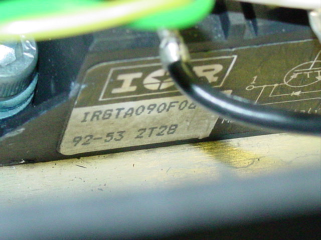
International Rectifiers IN-A-PAK IRGTA090F02
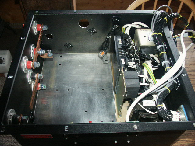
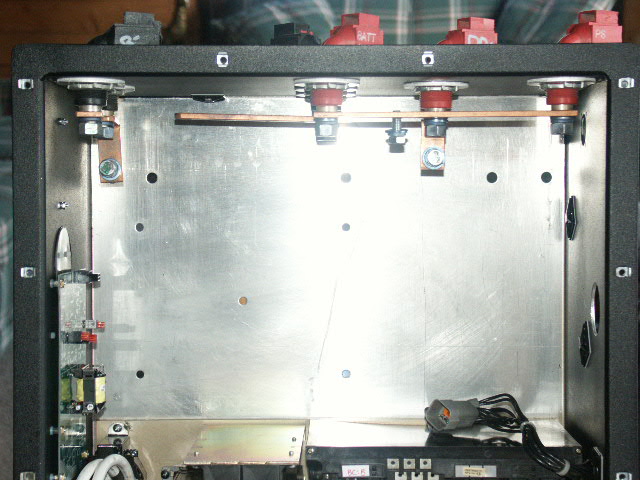
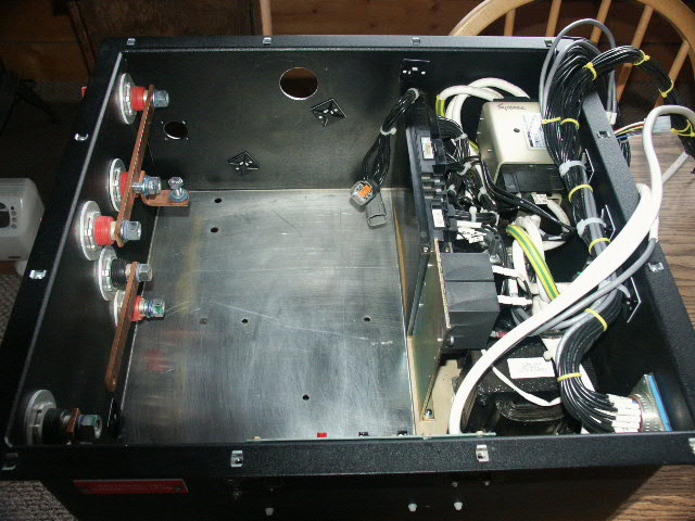
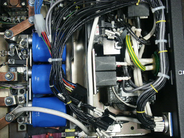
The TEVans setup positions the controller on the left side of the case, shown here gutted, and the charger electronics populate the right side of the case. The two sides are split in the middle by the two back to back logic cards. This photo is taken from the rear of the case.
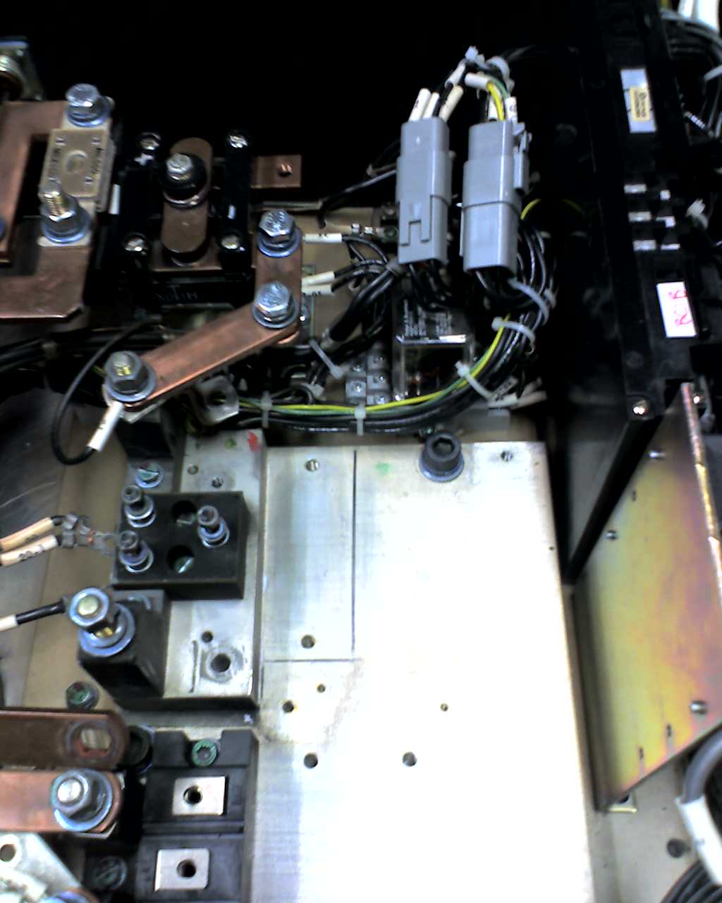
Progress as original controller components are removed.
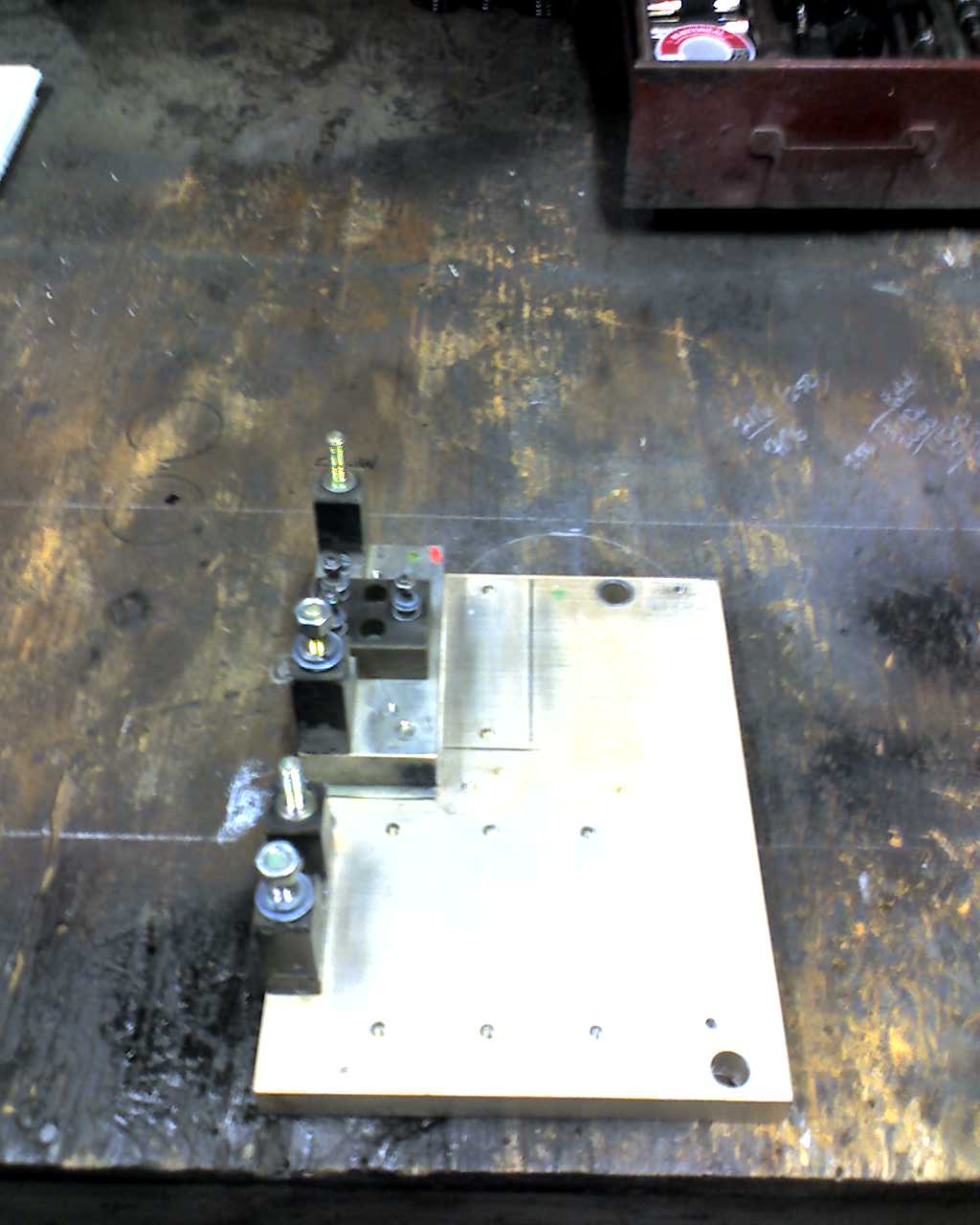
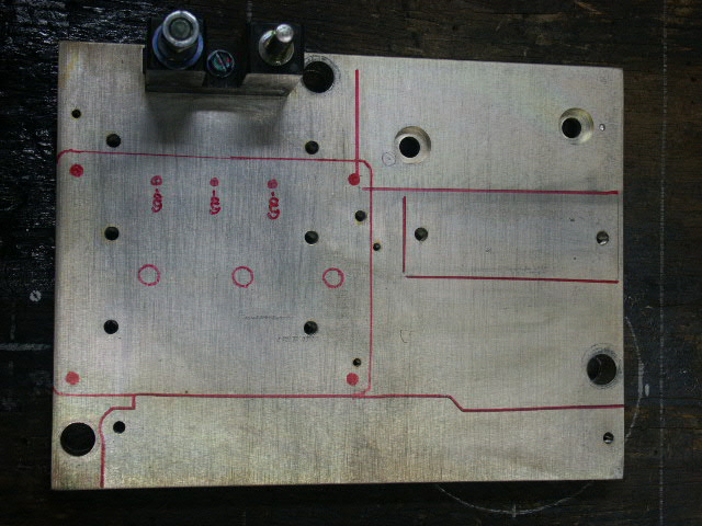
The original base-plate removed from the controller housing.
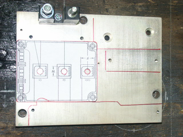
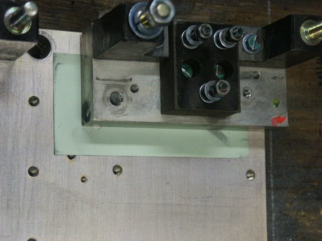
Here we are test fitting the new IGBT to the old base-plate design showing the proposed new IGBT layout. Note the sizing issues and overlaps which forced us to move to a new base-plate design.
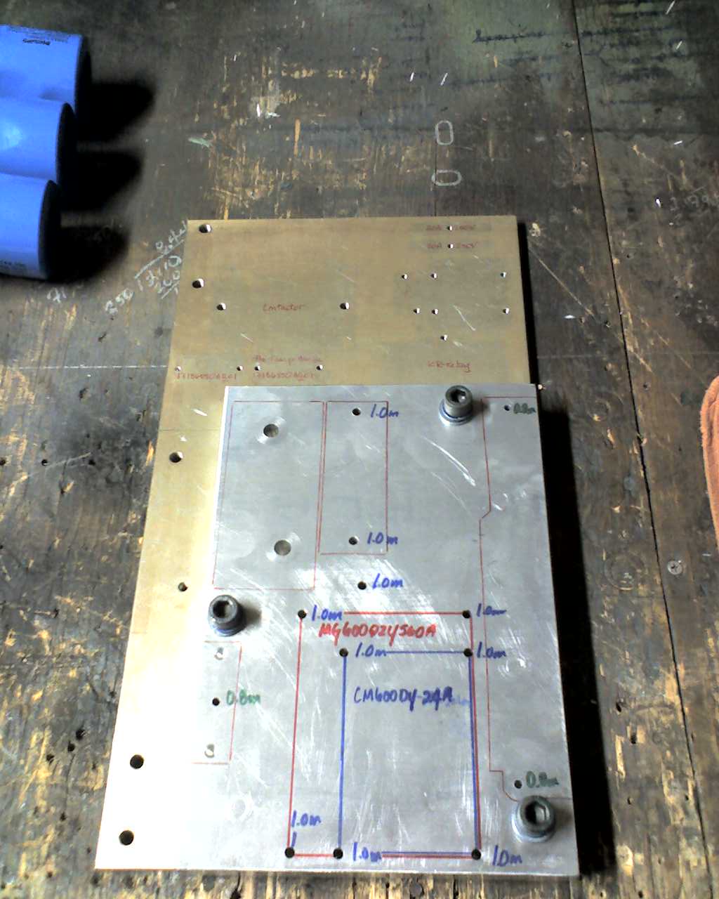
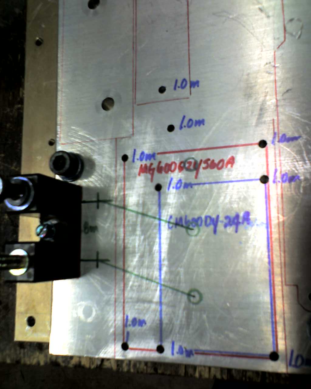
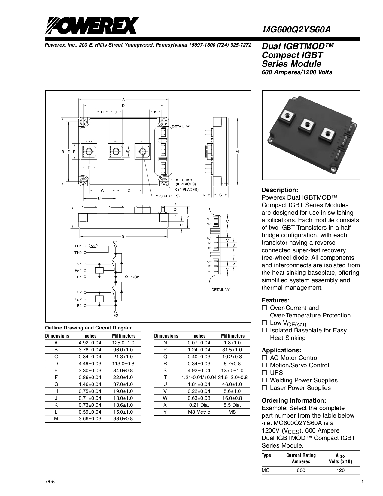
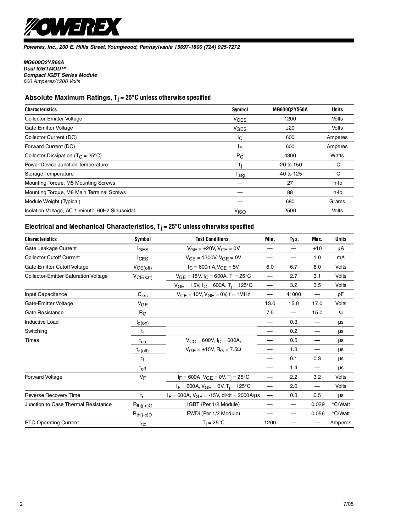
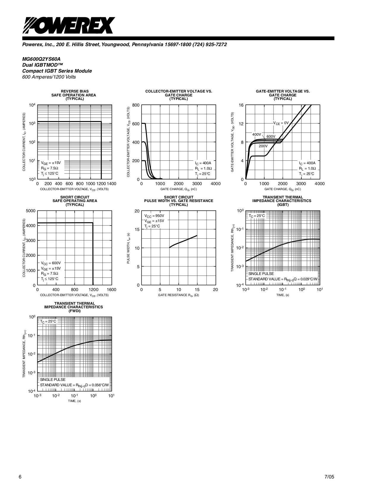
This photo shows a the now new base-plate and more test fittings. Note that we considered two different IGBT sizes denoted by the red and blue lines, and settled on the more robust IGBT, the MG600Q2YS60A, for final installation. We chose the MG600Q2YS60A for its extra protections and reputation, although it is no longer in production the surplus market has ample supplies.
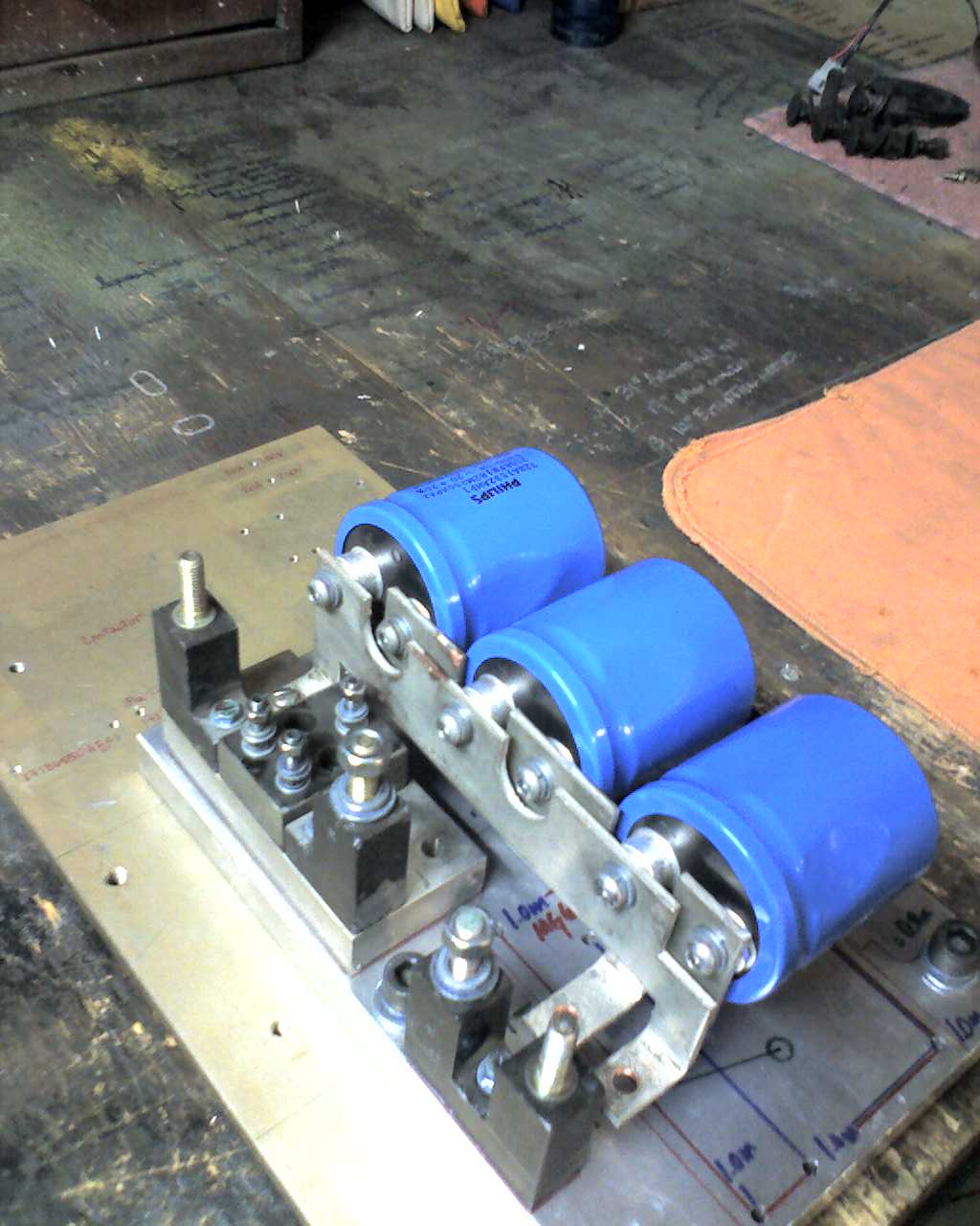
Test fitting components to be reused on the new base-plate.
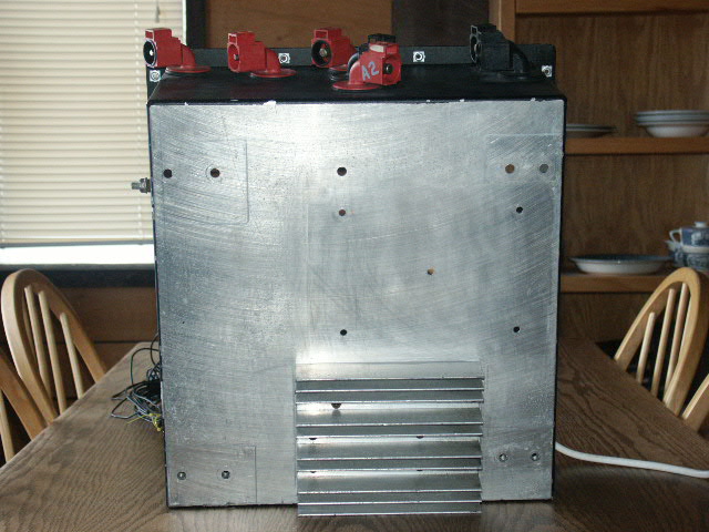
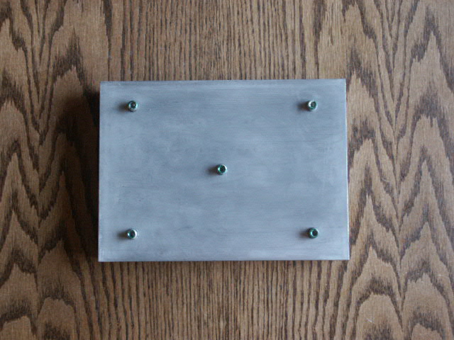
The bottom of the controller suitcase showing the positioning of various heat-sinks.
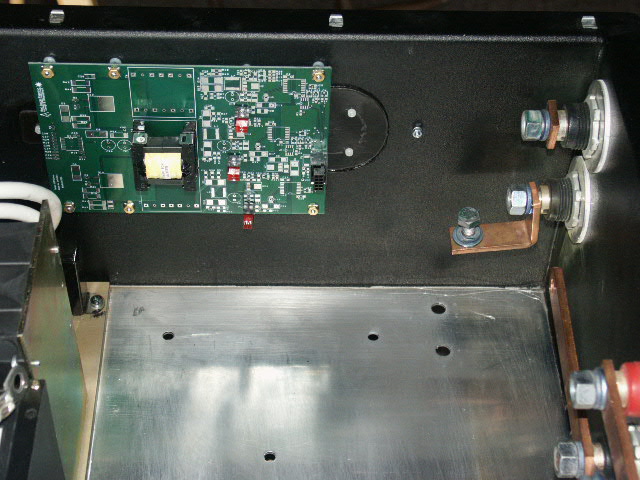
The original controller suitcase cleaned for rebuilding. Note the new IGBT driver card bottom left on the sidewall.
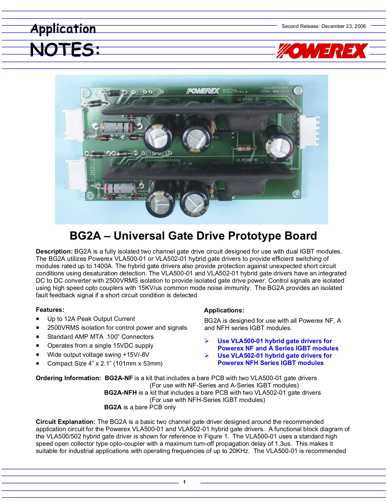
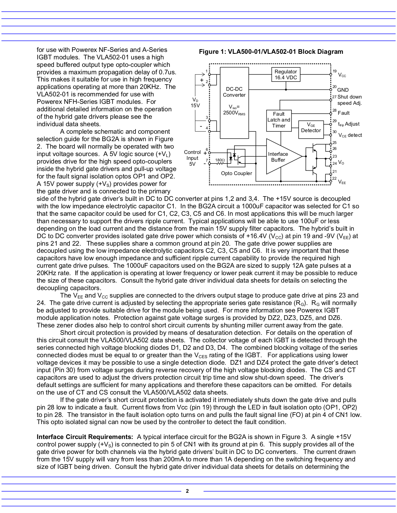
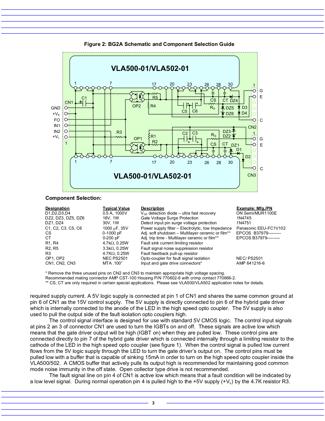
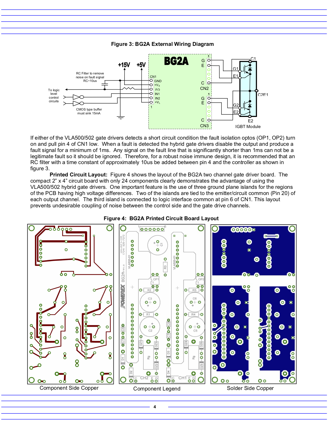
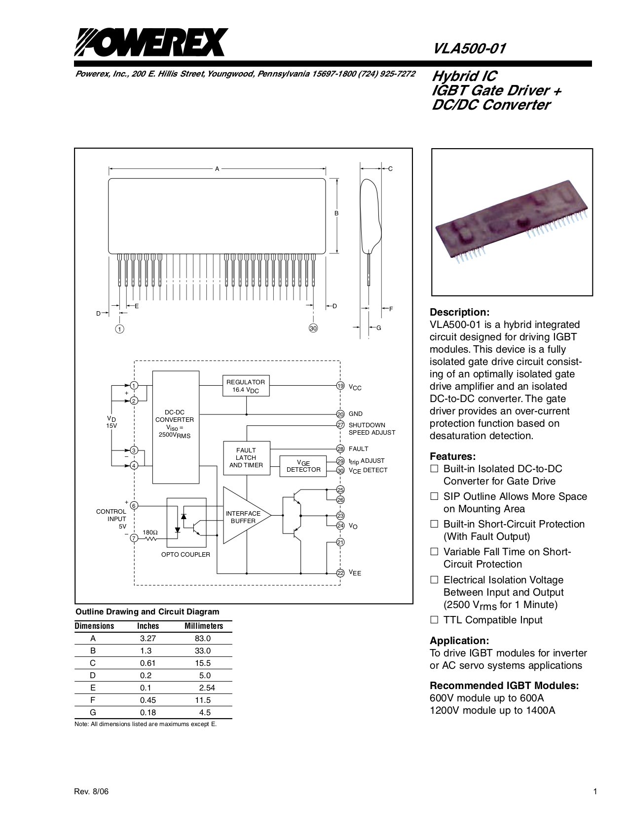
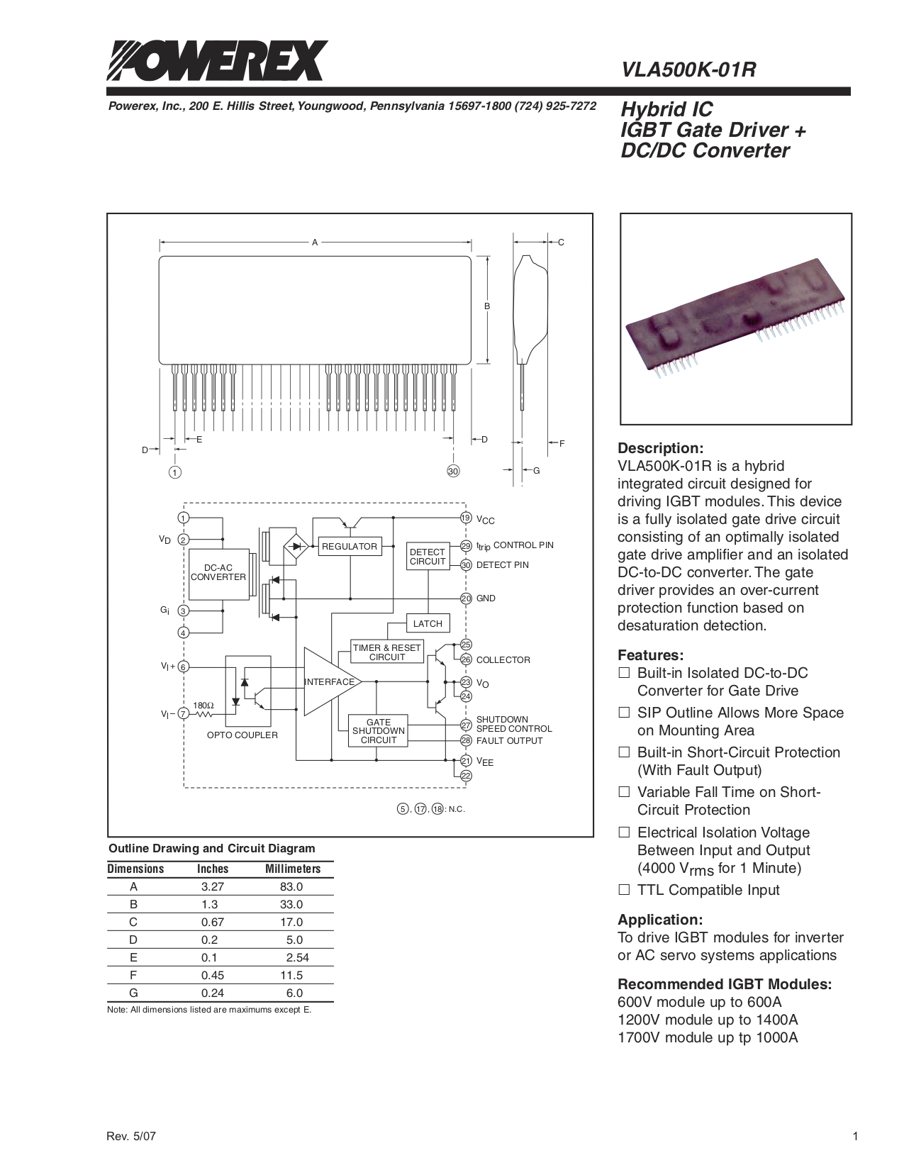
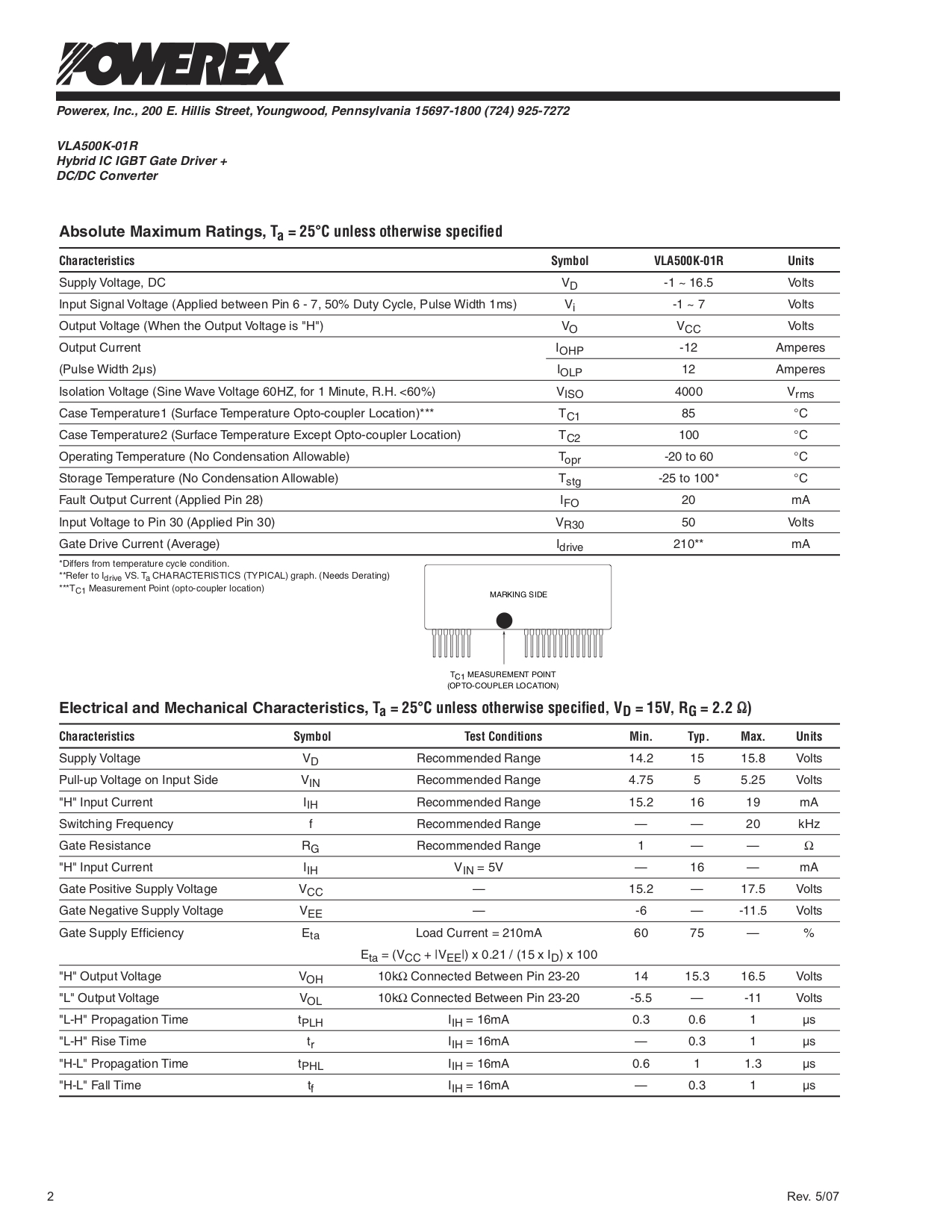
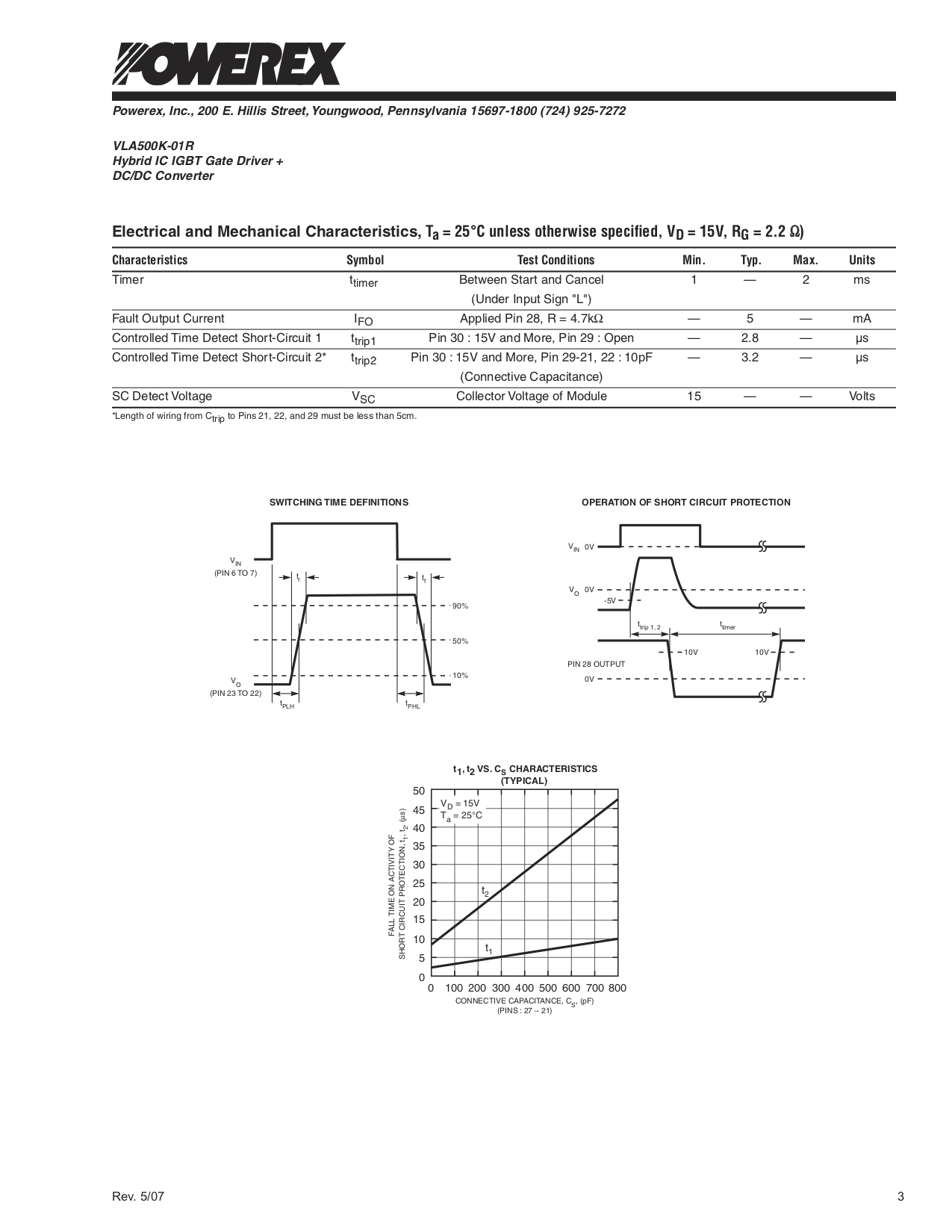
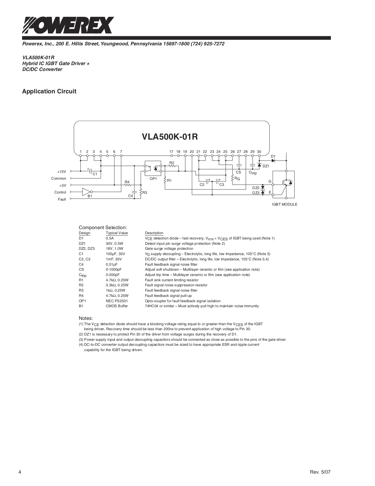
Here the new driver card is test fitted to the side plate over the area formerly used by LXT gauge. The driver card, as pictured, is yet to be stuffed. The design calls for the original logic card to continue running all standard operations, and the new driver card to take over all IGBT power control functions. The TEVans achilles-heel was the triple IN-A-PAK IGBT power-side functions and IGBT drivers which caused repeated controller failures in the original design.
A heat-sink after cleaning.
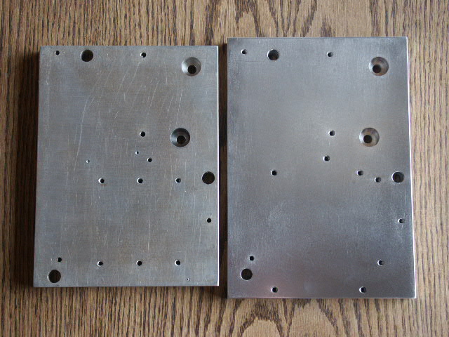
Old baseplate on left, new on right.
Refitting of original components to the new base-plate.
New base-plate fitting into original suitcase.
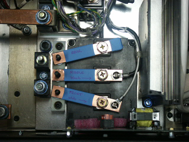
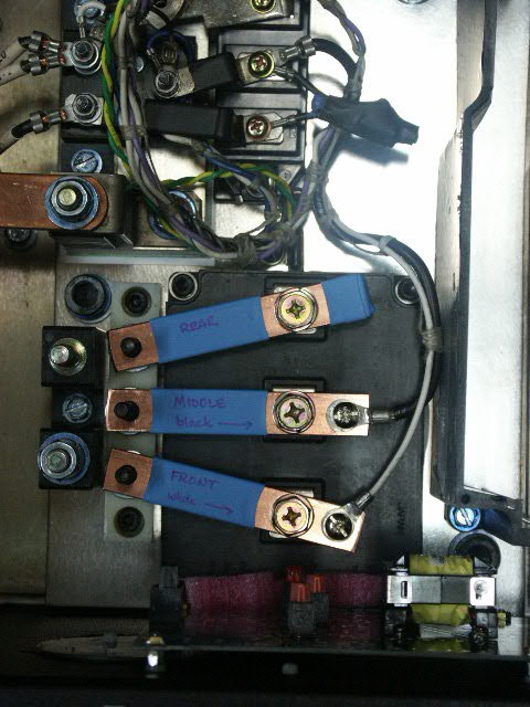
Note the new MG600Q2YS60A IGBT to the left, replacing the original triple IGBT configuration.
This view shows the new IGBT installed as well as the custom isolation block to its left. The isolation block replaces the first row of the old triple IN-A-PAK IGBT set-up. Note the drive logic card to the bottom of the picture.
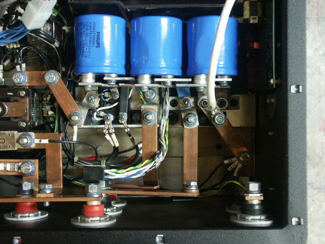
The following shots show most the major components installed. Next steps include stuffing the drive board, re-wiring the old logic car, wiring between the old and new PCBs and testing, lots of testing.
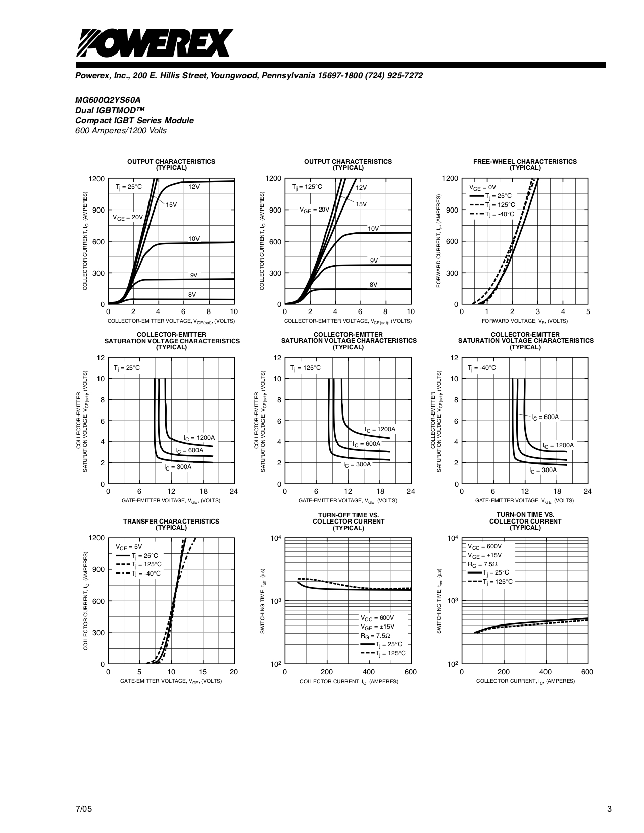
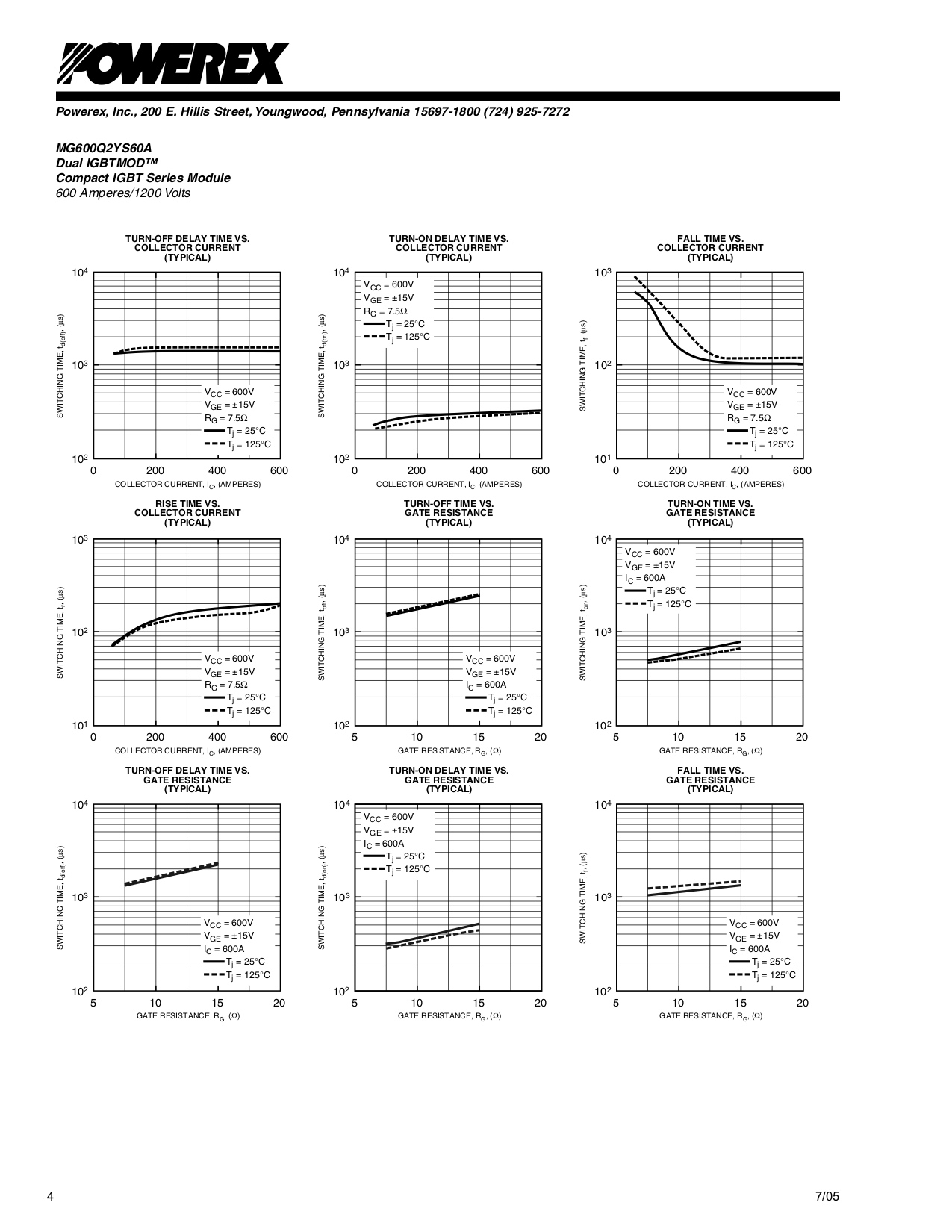
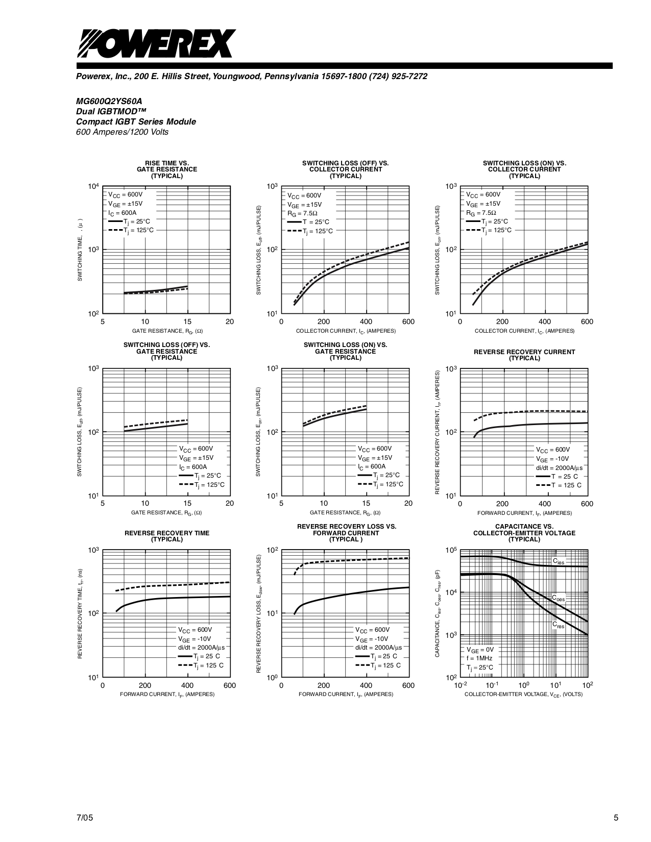
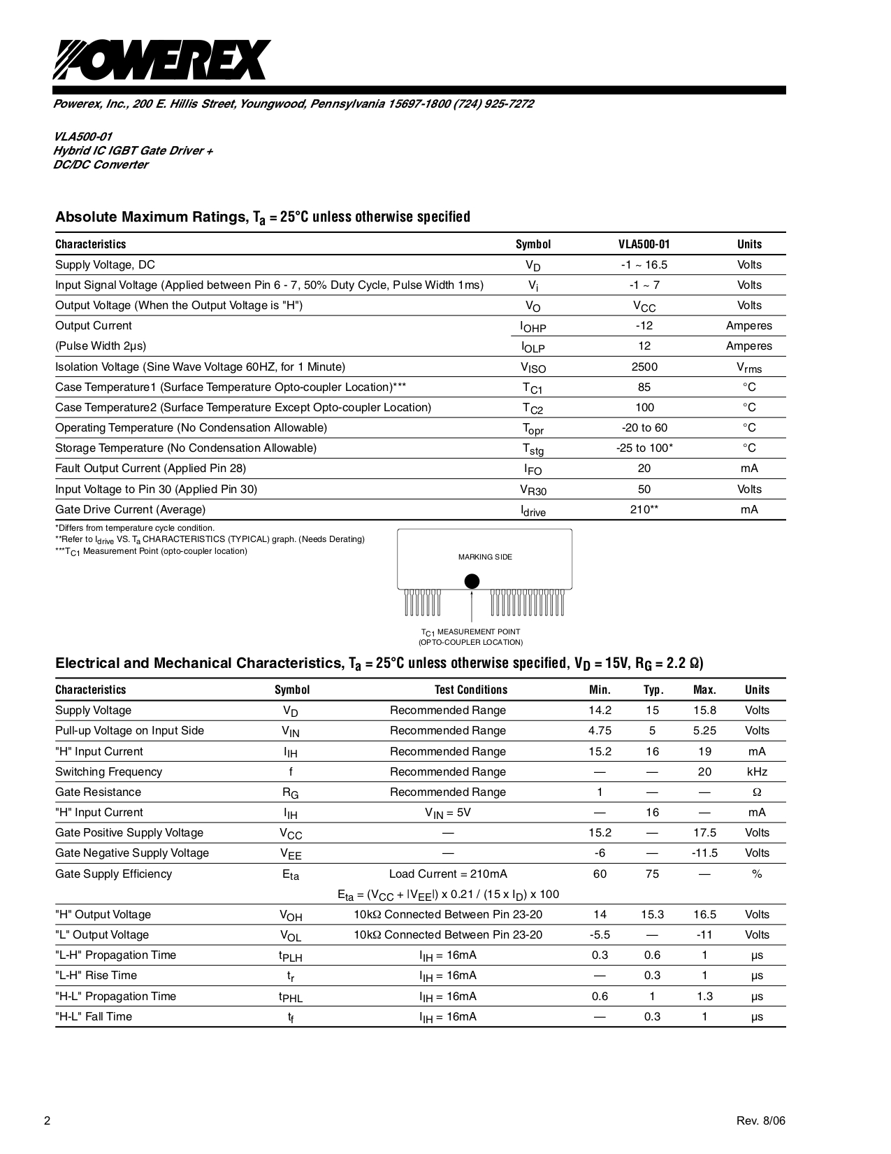
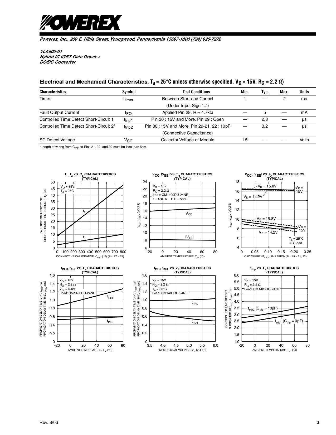
MG600Q2YS60A IGBT Data Sheet
